

Views: 0 Author: Site Editor Publish Time: 2026-08-24 Origin: Site


The commercial success of a new pet product hinges not just on consumer appeal, but on the structural architecture chosen before the first steel tool is cut. Product teams must balance end-user demands against the severe capital expenditure realities of large-scale injection molding. Feline behavioral standards require significant physical dimensions, while owners demand seamless hygiene and odor control. Deciding between a monolithic, one-piece design and a modular, multi-part assembly fundamentally alters the trajectory of mold development. This guide breaks down how architectural choices impact tooling requirements, press tonnage limits, assembly logistics, and long-term product scalability. You will learn how to align your structural design with your manufacturing capabilities to ensure a successful product launch.
Tooling CapEx vs. Assembly OpEx: One-piece designs require massive, expensive molds and high-tonnage presses, but eliminate assembly labor. Multi-part designs reduce initial tooling costs and press size requirements but introduce ongoing assembly and tolerance management costs.
Draft Angles and Deep Draws: A one-piece cat litter box with high walls requires significant draft angles and complex ejection systems to prevent vacuum sticking and part deformation during manufacturing.
Tolerance and Hygiene Risks: Multi-part architectures must account for fluid dynamics; poor tolerance control at the seams between bases and lids creates unhygienic leak points that drive negative consumer reviews.
Packaging and Logistics: Multi-part designs can often be nested or flat-packed, drastically reducing shipping and warehousing costs compared to bulky, non-nesting one-piece units.
Establish the baseline requirements for a commercially viable cat litter box based on veterinary and behavioral standards. The length must typically be one and a half times the size of the cat. This requires a large physical footprint. A larger surface area directly translates to a larger mold base. It also requires a higher clamping force during the injection molding process. You must secure access to heavy-duty machinery to accommodate these dimensions. The physical size of the product dictates the entire manufacturing strategy, from the steel block dimensions to the factory floor layout.
When defining these criteria, engineers must look beyond simple dimensions. The structural integrity of a large plastic basin depends heavily on wall thickness and ribbing. A massive flat bottom will warp without proper support. You must design structural ribs that provide rigidity without causing sink marks on the visible interior surface. This balancing act requires precise mold flow analysis before any steel is cut.
Cats prefer clear visibility to monitor their surroundings while using the box to prevent perceived ambushes. Consumer demand for translucent components necessitates specific polishing standards. You must achieve an SPI A-2 high-gloss polish for clear parts. This limits resin choices to clear or translucent materials like Polycarbonate or Acrylic. These materials require precise temperature control during molding to prevent clouding and structural degradation.
Cats that spray require tall, seamless walls. Designing high-sided walls influences mold core height. It demands advanced ejection systems to push the deep part off the core without causing damage. The material must flow evenly across these tall vertical sections without cooling too quickly. If the plastic cools before filling the cavity, you get short shots. Maintaining a consistent melt temperature across a massive tool requires a sophisticated hot runner system.
Specify high-flow resins to ensure complete cavity filling on deep-draw components.
Implement multi-zone temperature controllers for hot runner systems to prevent material degradation.
Select steel grades like S136 for optical components to maintain high-gloss finishes over long production runs.
Design venting channels at the end of fill locations to prevent gas traps and diesel burns.
Large footprints dictate the maximum physical dimensions of the mold base. The steel block required for a large basin is exceptionally heavy and requires specialized handling equipment. Odor control and cleanability depend on smooth, continuous internal surfaces. You must prevent waste buildup by dictating gate placement and parting line locations away from the interior basin. The interior must remain perfectly smooth.
Litter scatter and tracking prevention often require incorporating grate paths, top-entry grids, or built-in steps. These intricate geometries catch litter from paws before the cat exits. These features require bypass steel and high-precision shut-offs in the tool. Precision machining prevents flash from forming in the grid holes, which would otherwise require manual trimming. Manual trimming adds unacceptable labor costs and creates inconsistent product quality.
Feature | Mold Requirement | Manufacturing Challenge |
|---|---|---|
High Walls | Deep core machining, high draft angles | Vacuum sticking during ejection |
Clear Lids | SPI A-2 polish, S136 steel | Maintaining optical clarity, preventing scratches |
Sifting Grates | Bypass steel, precise shut-offs | Flash formation, rapid tool wear |
Smooth Interior | Hidden gate placement, SPI A-3 finish | Complex runner design, potential flow marks |
High-sided boxes require deep core and cavity machining. You must implement optimal draft angles to facilitate clean ejection. A draft angle of 2 to 5 degrees is typically required, depending on the exterior texture depth. Steeper angles prevent the plastic from scuffing against the steel during ejection. You must also address the risk of the plastic part creating a vacuum seal on the core. Deep draws require poppet valves or specialized air ejection systems to break the vacuum before the mechanical pins push the part off.
The cooling layout for a monolithic tool is highly complex. Heat concentrates in the deep corners of the core. If you do not extract this heat efficiently, the cycle time extends dramatically. Engineers use bubblers and baffles to push cooling water deep into the core structure. Conformal cooling channels, manufactured via 3D metal printing, offer superior thermal management but significantly increase the initial tooling investment.
Contrast the interior versus exterior finish requirements carefully. The interior must have a highly polished, low-surface-energy finish. An SPI-A3 finish prevents wet litter adhesion and eases daily scooping. The exterior requires a textured, premium finish to blend with home decor and resist scratching. Applying a Mold-Tech MT-11010 texture hides sink marks and provides a durable consumer-facing surface. Masking the mold to achieve two different finishes on a single part requires precise chemical etching processes.
Maintaining these finishes over hundreds of thousands of cycles requires proper steel selection. P20 steel is common for large bases, but it wears faster under heavy texturing. Upgrading to H13 or a pre-hardened equivalent ensures the texture remains crisp and the polished surfaces resist micro-scratching from the glass fibers often found in reinforced resins.
The projected surface area of a large, single-piece basin requires high-tonnage injection molding machines. You will often need presses rated for 800 to over 1,500 tons of clamping force. This massive force prevents the mold from blowing open when molten plastic is injected at high pressure. Relying on high-tonnage presses limits the pool of available contract manufacturers. It also increases the hourly machine rate, impacting your unit economics.
Moving a 1,500-ton mold requires heavy overhead cranes. Tool maintenance becomes a major logistical event. You cannot simply pull the tool from the press for a quick cleaning. Preventative maintenance schedules must be strictly enforced to avoid catastrophic tool failure, which would halt production entirely.
A one-piece architecture offers absolute structural integrity. There is zero risk of seam leakage, making it highly durable and hygienic. It requires zero assembly labor on the factory floor. However, it demands the maximum upfront tooling investment. Thick wall sections needed for structural rigidity lead to long cooling times, which extends the overall cycle time. Furthermore, shipping volumes are exceptionally high if the design does not allow for tight nesting during transport.
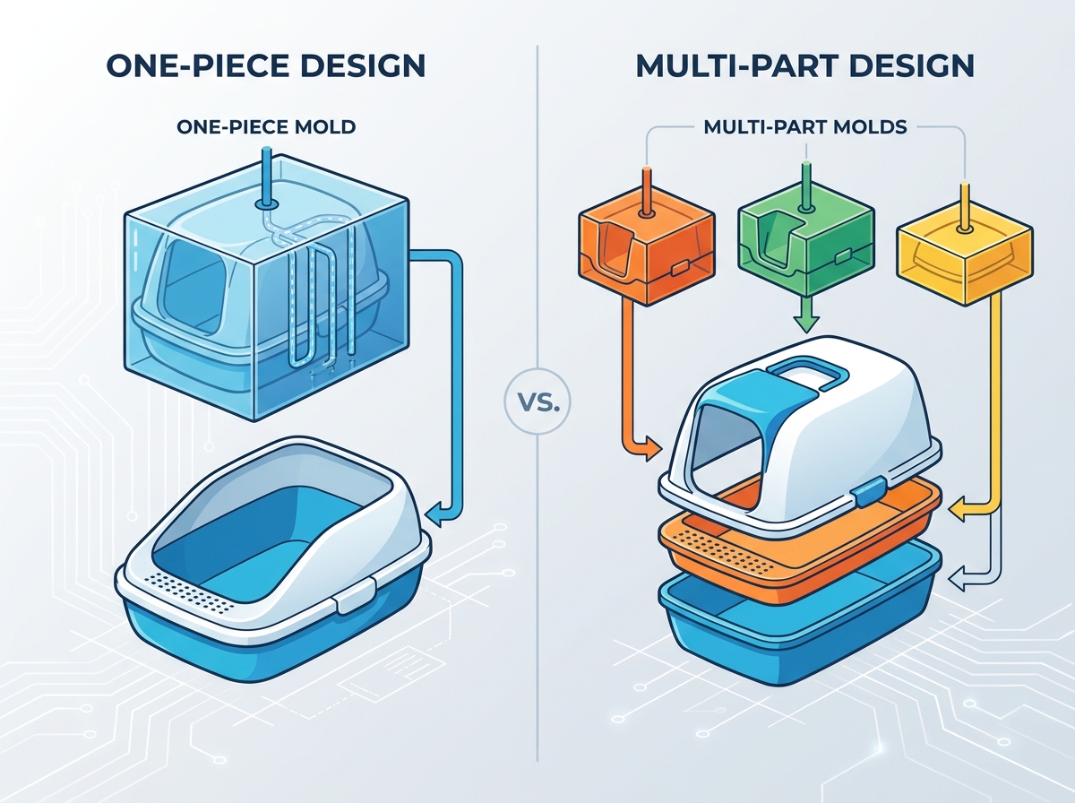
Breaking the product into modular components requires strict engineering for mating parts. You must design precise base pans, high-sided shields, top-entry lids, or sifting grates. Analyze the critical nature of snap-fits, living hinges, and overlap joints. These connections must prevent urine from seeping through the seams. Seam leakage is a primary failure point in multi-part designs. You must design overlapping joints that direct fluid back into the main basin, utilizing gravity to prevent capillary action.
Tolerance stack-up is a major concern. If the base shrinks slightly more than anticipated, and the lid shrinks slightly less, the snap-fits will not engage. You must conduct rigorous mold flow analysis to predict shrinkage rates accurately. Machining the tool steel slightly "metal safe" allows you to remove material later to dial in the perfect fit during the T1 sampling phase.
Evaluate the use of family molds versus dedicated single-cavity molds for each component. Family molds produce multiple different parts in one cycle, reducing machine time but complicating flow balancing. Dedicated custom pet product molds for each part offer better process control. Breaking the product into smaller parts allows for manufacturing on smaller, more common injection presses. Using 200 to 500-ton presses expands your manufacturing options and lowers hourly production rates.
When using dedicated tools, you can optimize the cycle time for each specific component. A thin-walled lid might run on a 30-second cycle, while the thicker base requires 50 seconds. Running them independently maximizes overall throughput and prevents the slower part from bottlenecking the faster one.
Designing integrated plastic grates for sifting requires complex mold tooling. The mold needs hundreds of small bypass shut-offs to form the holes. This demands superior steel quality, such as H13 steel, to prevent rapid wear and flash over time. Automated self-cleaning mechanisms require multi-part custom pet product molds for gears, motor housings, track lines, and electronic sensor compartments. These components demand tight engineering tolerances to prevent mechanical binding and system failure.
Gears and drive tracks require engineering-grade resins like Acetal (POM) or Nylon (PA66) for wear resistance and low friction. These materials shrink differently than standard Polypropylene. You must design the molds specifically for the chosen resin's shrink rate. You cannot simply swap materials later without risking severe dimensional inaccuracies.
Multi-part designs allow you to mix materials within the same product. You can pair an opaque, impact-resistant Polypropylene base with a clear, scratch-resistant Acrylic lid. This hybrid approach maximizes functionality while controlling material costs. It also simplifies offering multiple colorways. You only need to swap the resin in one component's mold to create a two-tone aesthetic, avoiding the need to purge large, single-color machines entirely.
Utilize Polypropylene for the main basin to resist chemical degradation from ammonia.
Incorporate TPE overmolding on the base feet to prevent sliding on hard floors.
Use Polycarbonate for swinging doors to withstand repeated impact from pets.
Apply ABS for motor housings in automated units to provide structural rigidity and flame retardancy.
Compare the high initial sunk cost of a one-piece mold against the lower tooling cost of a multi-part design. A monolithic tool requires massive blocks of steel and extensive CNC machining time. Multi-part tools are smaller and faster to cut. However, multi-part designs incur higher per-unit labor and assembly costs. You must calculate the break-even volume where the assembly labor exceeds the initial tooling savings.
Consider the cost of quality control. Multi-part assemblies require inspection at every mating point. If a worker fails to snap a lid correctly, the product fails in the field. One-piece designs eliminate this assembly variable, streamlining the quality assurance process and reducing scrap rates on the assembly line.
Volumetric weight implications heavily influence logistics. Multi-part designs can be shipped disassembled in smaller, flat boxes. They can also be nested tightly together. This drastically reduces ocean freight costs from overseas manufacturers. It also lowers final-mile e-commerce shipping fees. Bulky, non-nesting one-piece units ship a lot of empty air, maximizing freight penalties.
Optimizing pallet density is critical. A flat-packed multi-part design might allow 200 units per pallet, while a monolithic design only allows 40. This difference cascades through the entire supply chain, affecting warehouse storage requirements, container utilization, and ultimately, the landed cost of the product.
Design Architecture | Tooling Investment | Assembly Labor | Shipping Efficiency | Leak Risk |
|---|---|---|---|---|
One-Piece Monolithic | High | None | Low (unless nestable) | Zero |
Multi-Part Modular | Moderate | High | High (flat-packable) | Moderate (requires tight tolerances) |
Multi-part architectures support future product line expansions with minimal new investment. You can use a shared base mold across multiple product tiers. By swapping insert molds or creating new accessory molds, you can offer a top-entry lid, a front-entry door, or an open splash-guard. This modular ecosystem extends the life of your core tooling and allows rapid response to changing consumer preferences.
You can launch a basic open-top model first. Once market traction is proven, you can invest in the tooling for a hooded attachment. This phased approach mitigates risk and aligns capital expenditure with actual revenue generation, rather than sinking all funds into a complex monolithic tool on day one.
Large, flat bases are highly susceptible to bowing or warping during the cooling phase. Uneven cooling causes internal stresses that pull the plastic out of shape. You must mitigate this by incorporating structural ribbing on the underside of the base. Optimize the cooling channel design using conformal cooling techniques to extract heat uniformly. Selecting low-shrinkage resins also minimizes dimensional changes after the part drops from the press.
Gate location heavily influences warpage. Injecting plastic from a single central point on a large flat part creates radial flow patterns that induce stress. Using multiple gate locations, controlled by a sequential valve gate system, allows you to balance the fill pressure and reduce the internal stresses that lead to bowing.
Sharp flash on multi-part seams poses a safety hazard to pets. It also disrupts the aesthetic of premium products, making them look cheap. Flash occurs when plastic forces its way between the mating surfaces of the mold halves. Mitigation requires strict tooling tolerances and regular mold maintenance. You must also calculate precise clamping forces to ensure the press holds the mold completely shut during high-pressure injection.
Parting line mismatch occurs when the two halves of the mold do not align perfectly. This creates a noticeable step on the finished part. Robust guide pins and interlocking features on the mold base prevent lateral shifting during the injection cycle, ensuring a seamless transition across the parting line.
Evaluate exactly where molten plastic is injected into the mold. The gate leaves a small mark, or vestige, when the part is separated from the runner system. Gate marks must be hidden on the exterior bottom to maintain a premium finish. Keeping the gate away from the interior ensures the basin remains perfectly smooth for scooping. Improper gate placement can also cause flow marks and weld lines on highly visible cosmetic surfaces.
Hot runner systems eliminate the cold runner entirely, reducing material waste and cycle time. Valve gates provide the cleanest cosmetic finish, as a mechanical pin shuts off the plastic flow flush with the part surface. While more expensive initially, valve gates are essential for premium products where visual defects are unacceptable.
Audit your current shipping container utilization rates to determine if flat-packing a multi-part design yields higher freight efficiency.
Request a Design for Manufacturability (DFM) analysis from your tooling engineer to identify potential draft angle conflicts.
Specify exact SPI and Mold-Tech surface finish requirements on your 2D drawings before cutting steel.
Run mold flow simulation software to pinpoint optimal gate locations and minimize warpage on large flat base panels.
A: Tooling expenses vary significantly based on the chosen architecture. A single, massive cavity for a one-piece design requires a large steel block and extensive machining, driving up initial capital expenditure. Multi-part designs utilize smaller, less expensive molds, but you must purchase multiple tools. The inclusion of complex slides, lifters, and hot runner systems will further increase the total investment required.
A: Polypropylene (PP) is highly recommended for the main basin due to its excellent chemical resistance to ammonia, high impact strength, and overall cost-effectiveness. For components requiring transparency, such as structural lids or swinging doors, Polycarbonate (PC) or Acrylic (PMMA) are ideal choices because they offer clarity and scratch resistance.
A: Leaks occur when urine seeps through the seams between the base and the upper walls via capillary action. Mold design fixes this by engineering precise overlapping joints. The upper wall must overhang the interior of the base pan, directing all fluid downward. Tight mold tolerances are mandatory to ensure these mating surfaces fit seamlessly without gaps.
A: A minimum draft angle of 2 to 5 degrees is required for deep draws. This taper allows the deep plastic basin to release from the steel core without creating a vacuum or scuffing the surface. Heavier exterior textures require steeper draft angles to eject cleanly without dragging and ruining the cosmetic finish.
A: The standard timeline spans several months. It typically begins with 2 to 4 weeks dedicated to Design for Manufacturability (DFM) and final mold design. Following approval, the actual steel cutting and tool assembly take 4 to 8 weeks. Finally, allow 2 to 3 weeks for initial sampling (T1 trials), adjustments, and final surface texturing before mass production begins.


