

Views: 0 Author: Site Editor Publish Time: 2026-09-15 Origin: Site


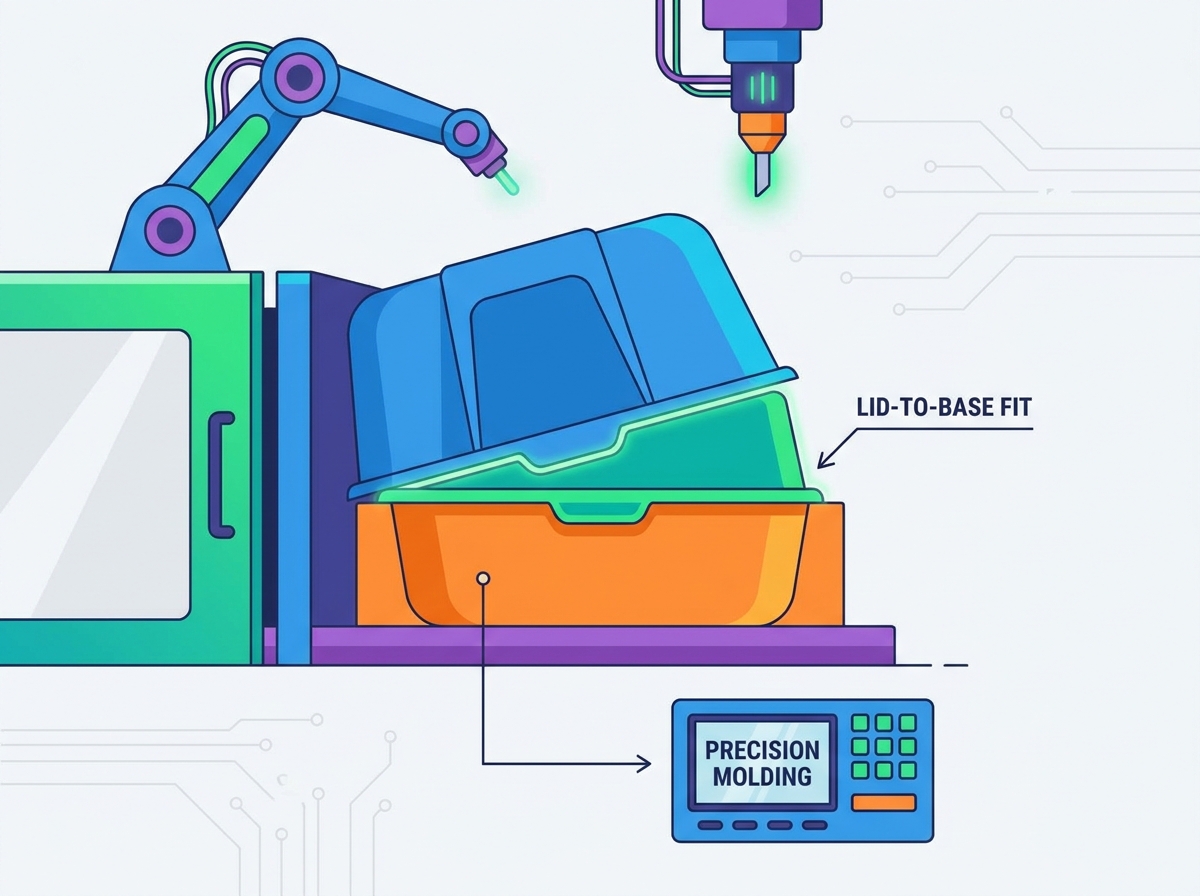
Manufacturing large, thin-walled plastic components presents a distinct engineering challenge on the production floor. Mating two expansive surfaces requires absolute precision. Even minor warpage results in assembly failure or immediate consumer product rejection. When producing a hooded enclosure, the lid and base must align flawlessly. A misaligned seam compromises the structural integrity and functionality of the entire unit.
Poor lid-to-base fit in a hooded cat litter box leads to critical product failures. Consumers frequently encounter urine leakage at the seam when gaps exceed design tolerances. Loose joints create micro-environments for mold and bacterial accumulation. Furthermore, misaligned snap-fits often break under stress. Structural failure becomes a severe risk when consumers lift a fully loaded base by the hood handle.
Overcoming these defects requires rigorous Design for Manufacturability (DFM). Precise tooling and controlled injection molding parameters ensure dimensional stability. Manufacturers must prioritize hygiene and seamless assembly from the initial CAD phase to the final production run.
Achieving a flush lid-to-base fit requires managing differential shrinkage across large surface areas through optimized gate placement and uniform cooling.
Investing in high-precision custom cat litter box molds with robust interlocking features prevents core shift during injection and ensures long-term part repeatability.
Material selection (typically Polypropylene or ABS) directly dictates the required tooling tolerances, part transparency, and pack-and-hold processing parameters.
Hygiene-first design at the tooling level (eliminating tight moisture traps) prevents mold growth, a primary driver of consumer returns.
Evaluating a molding partner must center on their capability to perform advanced mold flow analysis and post-molding dimensional verification (CMM).
Large plastic parts undergo complex physical changes during the cooling phase. Differential cooling occurs when sections of the plastic solidify at varying rates. The hood and base of a large enclosure possess expansive surface areas that dissipate heat unevenly. This thermal imbalance generates significant internal stress. When you pull a part from the press too early, that stress releases, twisting the geometry out of spec.
Uneven wall thickness and sharp corners exacerbate these residual internal stresses. Material shrinks toward the center of its mass as it cools. Thicker sections cool slower, pulling material away from thinner, already-solidified areas. This dynamic manifests as warpage immediately after ejection from the mold. You will see the edges bow inward or flare outward, making assembly impossible.
Deep-draw geometries further complicate the molding process. High-sided bases and tall domes require substantial draft angles for proper part ejection. Inadequate draft causes the part to stick to the core, inducing mechanical stress during ejection. This forced removal warps the plastic, permanently distorting the mating edges. We typically specify a minimum of 1.5 to 2 degrees of draft per side for these depths.
Verify uniform wall thickness across the entire CAD model before cutting steel.
Increase draft angles on deep-draw sections to minimize ejection force.
Radius all internal corners to reduce stress concentrations during cooling.
Implement a stepped cooling cycle to manage thermal gradients.
A functional seam demands exact dimensional tolerances. Engineers typically target a gap allowance of +/- 0.5mm across the entire mating perimeter. Any deviation beyond this threshold prevents the latches from engaging correctly and compromises the fluid seal. We measure this using a coordinate measuring machine (CMM) on the first off-tool samples.
Structural load-bearing requirements dictate the mechanical demands on snap-fits and latches. These components must hold the weight of a fully loaded base filled with heavy clay. When a user lifts the unit by a hood-mounted handle, the latches bear the entire dynamic load. Failure here results in the base dropping and shattering. The latch geometry must incorporate a positive lock angle.
Sanitation and moisture management require specific design criteria. The mating seam must prevent liquid capillary action. Tight, inaccessible crevices trap moisture and organic waste. Designing out these traps prevents mold propagation and ensures the product remains hygienic over its lifecycle. We use overlapping drip edges to direct fluids back into the main basin.
Gate location directly impacts material flow length and pressure drop within the cavity. Placing the gate centrally on a large dome minimizes the maximum flow distance. This reduces the pressure required to fill the extremities, lowering internal molded-in stress. We often use a single large sprue gate or a multi-drop hot runner system depending on the press capacity.
Engineers must evaluate edge gating versus hot runner systems for large parts. Hot runner systems maintain resin temperature throughout the delivery channel. This approach optimizes flow orientation and controls the shrinkage direction in the tool. Edge gating often results in longer flow paths and higher pressure requirements, which increases the risk of flash and short shots.
Avoiding knit lines near critical structural points is paramount. Weld lines form where two flow fronts meet, creating a localized weak point. Tooling designers must position gates so that these lines do not intersect with snap-fit latches or handle mounts. Mechanical strength at these junctions prevents catastrophic product failure. We run mold flow simulations specifically to map and move these weld lines.
Gate Type Comparison for Large Enclosures | ||||
Gate Type | Flow Control | Pressure Drop | Tooling Cost | Best Application |
|---|---|---|---|---|
Direct Sprue | Low | Low | Low | Thick-walled bases |
Edge Gate | Moderate | High | Moderate | Flat, shallow components |
Hot Runner (Valve) | High | Low | High | Large, thin-walled hoods |
Conformal cooling channels follow the exact geometry of the part. Traditional straight-line drilled channels fail to cool deep-draw sections uniformly. Conformal cooling ensures the core and cavity cool at identical rates, stabilizing the polymer chains simultaneously. We use metal 3D printing (DMLS) to create these complex channel inserts for the highest heat-transfer areas.
Mitigating hot spots prevents the base from bowing inward. When the inner core retains heat longer than the outer cavity, the plastic shrinks toward the hotter surface. Uniform cooling prevents the hood from flaring outward, ensuring the mating edges remain perfectly parallel. We monitor tool temperatures with infrared cameras during the initial sampling runs.
High-pressure injection forces can displace the mold core. Taper locks and heavy-duty guide pins prevent core shift during the injection phase. These interlocking features lock the two halves of the tool rigidly in place. Without them, the injection pressure will push the core off-center, ruining the part geometry.
Tooling deflection directly causes wall thickness variations. A shifted core creates a thin wall on one side and a thick wall on the opposite side. This variation leads to unpredictable shrinkage and mismatched mating surfaces, rendering the assembly useless. We specify H13 tool steel for the core blocks to resist this deflection under tonnage.
Seam geometry must prioritize self-draining mating lips. Overlapping nested joints direct liquid back into the pan rather than allowing it to pool in the seam. This geometry relies on gravity to maintain sanitation. We design the upper hood lip to sit inside the lower base channel, creating a physical barrier against leaks.
Integrating radiused corners instead of sharp 90-degree transitions allows for easy consumer wipe-downs. Sharp corners trap debris and create micro-environments for mold growth. Smooth, sweeping curves in the tool design eliminate these hazards entirely. We polish these internal radii to an SPI A2 finish to further prevent waste adhesion.
Semi-crystalline polymers like Polypropylene (PP) exhibit different shrinkage behaviors compared to amorphous polymers like ABS. PP shrinks significantly more as its crystalline structure forms during cooling. ABS provides higher dimensional stability and tighter tolerances out of the mold. You have to size the tool cavity specifically for the resin you plan to run.
PP offers excellent chemical resistance, which is necessary for withstanding acidic environments. It also provides the flexibility for living hinges and snap-fits. However, its higher and less predictable shrinkage requires precise tooling compensation. ABS yields stiffer parts with lower shrinkage but lacks the chemical resilience of PP. We often see stress cracking in ABS parts exposed to harsh cleaning chemicals.
Material selection impacts aesthetic requirements. Translucent or transparent hoods demand specific molding parameters. Clear grades of PP require optimized cooling rates to prevent clouding, while clear ABS alternatives offer better optical clarity but demand higher injection pressures. You must balance the visual requirements with the mechanical performance.
Material Comparison for Large Enclosure Molding | ||||
Material | Shrinkage Rate | Chemical Resistance | Dimensional Stability | Flexibility (Snap-fits) |
|---|---|---|---|---|
Polypropylene (PP) | 1.0% - 2.5% | Excellent | Moderate | High |
ABS | 0.4% - 0.8% | Moderate | High | Low |
HDPE | 1.5% - 3.0% | Excellent | Low | High |
Resin additives alter the isotropic versus anisotropic shrinkage behavior of the chosen material. Nucleating agents speed up the crystallization process in PP. This rapid crystallization promotes more uniform shrinkage across the part, reducing warpage. We specify nucleated grades for large flat panels to keep them straight.
Impact modifiers and glass fillers change the structural dynamics of the plastic. Glass fibers restrict shrinkage along the direction of the flow. While this increases strength, it introduces severe anisotropic shrinkage, requiring advanced mold flow simulation to predict and counteract the resulting warp. We generally avoid glass-filled resins for these enclosures due to the unpredictable warp and poor surface finish.
Holding pressure compensates for volumetric shrinkage as the plastic cools inside the mold. Once the cavity fills, the machine packs additional material into the tool. This pressure forces the cooling plastic against the cavity walls, maintaining the intended dimensions. We set the hold pressure at roughly 50% to 70% of the injection pressure.
Operators walk a fine line between under-packing and over-packing. Under-packing causes sink marks, short shots, and loose snap-fits. Over-packing forces too much material into the cavity, causing flash, sticking, and severe molded-in stress that warps the part upon ejection. We use cavity pressure transducers to monitor and control this phase precisely.
Establish the short shot weight to determine the exact fill volume.
Increase pack pressure incrementally until sink marks disappear.
Monitor part weight to ensure consistent packing across shots.
Adjust hold time until the gate freezes off completely.
Measure the final part dimensions after 24 hours of cooling.
In-mold cooling time dictates the dimensional stability post-ejection. The part must reach a temperature where it is structurally rigid enough to withstand the ejection pins. Rushing the cooling cycle leaves the core of the plastic wall molten. We calculate cooling time based on the thickest wall section of the part.
Premature ejection risks severe part distortion. Manual handling or automated packaging lines can easily warp a part that has not fully set. Extending the cooling cycle ensures the mating edges lock into their final dimensions before leaving the press. We use robotic end-of-arm tooling (EOAT) to remove large parts evenly, preventing manual distortion.
Selecting a manufacturer requires strict verification of their engineering capabilities. Require evidence of Moldflow analysis before approving any tool design. Post-molding, mandate Coordinate Measuring Machine (CMM) inspection for first-article approval to verify the seam tolerances. You need hard data, not just visual inspections.
Assess the partner's ability to run physical stress tests. The molded latch assembly must survive dynamic load drops without cracking. Manufacturers should provide documentation proving the latches hold the specified weight under real-world lifting conditions. We require drop testing from a height of one meter with a fully loaded base.
Investing in P20 or H13 steel tooling with optimized cooling provides a strong long-term return on investment. Cheaper, unoptimized aluminum molds yield high scrap rates due to poor thermal management. The initial savings of aluminum tooling quickly evaporate through rejected parts and assembly failures. We only use aluminum for short-run prototypes.
Mandate a strict DFM review phase focusing specifically on the mating seam geometry. Finalize all load-bearing latch tolerances before cutting steel. This mitigation strategy prevents costly tool modifications and ensures the final product assembles flawlessly. We hold weekly engineering reviews during the tool build phase to track progress and verify design intent.
Audit your current CAD files to ensure draft angles and wall thicknesses support uniform cooling.
Request a comprehensive Moldflow analysis from your tooling partner to identify potential warpage zones before cutting steel.
Specify conformal cooling channels in your tool design requirements to guarantee dimensional stability across large mating surfaces.
Implement strict CMM inspection protocols for first-article approval, focusing on the +/- 0.5mm gap allowance at the seam.
A: Poor fit usually results from differential shrinkage and uneven cooling. If the wall thicknesses vary or the mold lacks proper cooling channels, the plastic warps upon ejection. This distortion alters the mating edges, preventing a flush assembly.
A: Tooling engineers must scale the mold cavity larger than the final part to compensate for shrinkage. Different resins shrink at different rates. If the tooling does not account for the specific isotropic or anisotropic shrinkage of the chosen polymer, the parts will not align.
A: Polypropylene (PP) is highly recommended. It offers excellent chemical resistance to acidic urine, high impact strength, and the flexibility required for durable snap-fit latches. However, its higher shrinkage rate requires precise tooling design.
A: Mold flow analysis simulates the injection process, predicting how the resin fills, packs, and cools. It identifies potential hot spots, weld lines, and high-stress areas. Engineers use this data to optimize gate placement and cooling layouts before building the mold.
A: Snap-fit latches generally require dimensional tolerances of +/- 0.1mm to +/- 0.2mm to ensure a secure lock. The overall mating seam typically requires a +/- 0.5mm gap allowance to maintain a fluid seal while allowing the latches to engage fully.
A: Conformal cooling channels follow the complex contours of the part, unlike straight drilled lines. This ensures all areas of the plastic, including deep draws and thick sections, cool at the exact same rate. Uniform cooling eliminates the internal stresses that cause warpage.
A: Effective seam geometry uses overlapping, self-draining lips that direct moisture back into the base. Eliminating sharp 90-degree corners and tight crevices removes the micro-environments where organic waste and moisture get trapped, preventing bacterial growth.


