

Views: 0 Author: Site Editor Publish Time: 2026-09-22 Origin: Site


The pet care market demands high-volume, durable products, but manufacturing slotted geometries like scoops and trapping grids presents unique tooling challenges. Poorly designed molds for slotted and grid-based products lead to high scrap rates, flash, weld lines, and premature tool wear. These defects directly impact unit economics and product durability on the production floor. When you run thousands of cycles a day, even minor tooling flaws compound into massive production bottlenecks.
Successfully scaling production requires a rigorous Design for Manufacturability (DFM) approach. You cannot simply cut steel and hope for the best. This guide breaks down the technical evaluation criteria for designing, tooling, and sourcing a cat litter scoop mold and related plastic pet accessory molds. We will look at draft angles, gate placement, tooling materials, and resin selection to ensure your next production run hits target cycle times without excessive scrap.
Draft Angles are Critical: Slotted geometries in scoops and litter-trapping grids require precise draft angles (typically 1.5° to 3°) to prevent ejection friction and part deformation.
Gate Placement Dictates Strength: Improper gating in grid designs creates weak weld lines; strategic gate placement is required to maintain structural integrity under load.
Tooling Material Defines ROI: High-volume production demands hardened steel (e.g., H13) to withstand the abrasive wear of continuous cycling, whereas aluminum may suffice for low-volume prototyping.
Resin Selection Alters Tooling Specs: Designing for standard resins (PP, ABS) versus high-performance or recycled plastics (PET, PEEK) requires different shrinkage allowances, thermal management strategies, and specialized heating systems in the mold.
Defining the engineering challenge starts with understanding the geometry. Scoops and litter-trapping grids are significantly more complex than standard open-and-shut molds. They require intricate core and cavity interlocking to form the sifting slots. When you inject molten plastic into a cavity with dozens of thin steel pins, the pressure dynamics change completely. The plastic flow wants to push those pins around, leading to core deflection. If the pins deflect, you get uneven wall thickness and flash.
You have to balance performance with manufacturability. Consumers want fine sifting capabilities, which means narrow slots. However, narrow slots require thin tool steel. Thin steel is fragile. If you design slots that are too narrow, the steel core pins will snap under injection pressure. We typically recommend a minimum slot width that allows for robust steel conditions, usually no less than 1.5mm depending on the draw depth. Sifting geometry and media compatibility also play a role. You must tailor slot widths and taper designs in the mold to handle diverse litter types. Clumping clay behaves differently than silica crystals or biodegradable pine pellets. If the taper is wrong, material stagnates during flow, causing short shots or burn marks.
System integration and accessory compatibility require precise tolerances. Engineering molds to include modular interfaces, such as snap-fits, hook attachments, and integrated mounting clips, means you are dealing with undercuts. These undercuts require lifters or sliders in the mold design. If you are building a scoop that snaps into a matching holder or a waste bin system, the shrinkage calculations must be dead-on. Scalability metrics dictate the project's success. You need to establish acceptable cycle times, target scrap rates below 1%, and tool life expectancy before initiating the tooling phase. For high-volume consumer goods, we aim for Class 101 molds designed for over one million cycles.
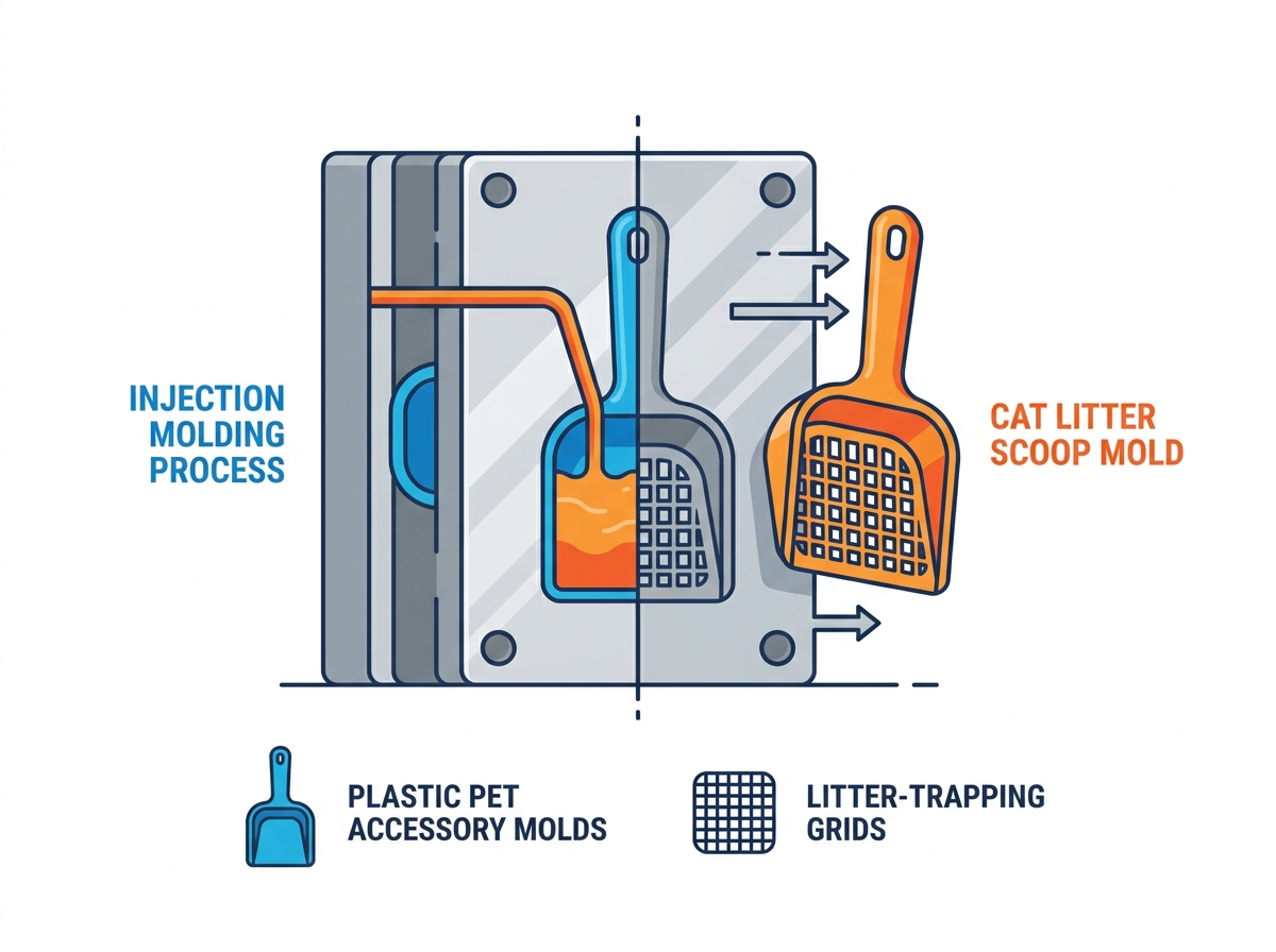
Maintaining uniform wall thickness across the scoop body prevents uneven cooling and warpage. When plastic cools, it shrinks. If you have a thick handle transitioning abruptly into a thin sifting basket, the thick section cools slower and pulls material from the thin section. This causes sink marks and severe warping. You must follow strict guidelines for transitioning from thicker handle sections to thinner sifting blades. Coring out thick sections is mandatory. Instead of a solid plastic handle, use a ribbed structure to maintain strength while keeping the nominal wall thickness consistent.
Calculating flow length-to-wall thickness ratios is critical for complex litter-trapping grids and micro-slotted patterns. If the flow length is too long for the given wall thickness, the plastic will freeze off before the cavity is full. This results in short shots. You have to run mold flow simulations to determine if your chosen resin can actually fill the grid pattern at the specified injection pressure and temperature.
Standard draft angles are insufficient for deep-draw scoops and dense grid patterns. When you have dozens of slots, the total surface area in contact with the steel is massive. This creates immense friction during ejection. Specifying draft angles for the internal slots ensures smooth ejection without pin push marks. We typically apply 1.5° to 3° of draft on all vertical faces forming the slots. If you apply texture to the scoop, you need an additional 1.5° of draft for every 0.001 inches of texture depth.
Evaluating ejection systems requires looking at the part geometry. Stripper plates are often superior to strategically placed ejector pins for fragile grid intersections. Ejector pins concentrate force on small areas, which can punch right through a warm, freshly molded grid. A stripper plate pushes evenly on the entire perimeter of the part. Integrating air-assist ejection helps prevent vacuum pull in deep-drawn cup-style scoops. When the mold opens, a vacuum can form between the core and the plastic part, making it stick. A quick blast of compressed air breaks that vacuum.
Designing structural ribs at the neck of the scoop, where the handle meets the basket, is necessary for strength. This is the highest stress point when a user digs into heavy, wet litter. However, you must design these ribs without causing sink marks on the cosmetic surface. Sizing rules for ribs dictate keeping rib thickness to 60-80% of the nominal wall thickness. If the main wall is 2mm thick, the rib base should not exceed 1.6mm.
Integrating ergonomic handle features into the primary mold design often involves overmolding considerations for rubberized grips or textured patterns. If you plan to overmold a TPE grip onto a PP handle, the primary mold must include precise shut-off areas to prevent the TPE from flashing over the rigid substrate. Designing mating tolerances and snap-lock features for modular, multi-piece scoop and holder assemblies requires strict adherence to shrinkage rates. The snap hook must flex without breaking, which means avoiding sharp internal corners that act as stress concentrators.
Feature | Design Guideline | Manufacturing Impact |
|---|---|---|
Wall Thickness | Maintain uniform thickness; core out thick areas. | Prevents sink marks, reduces cycle time, minimizes warpage. |
Draft Angles | 1.5° to 3° minimum on slotted grids. | Ensures clean ejection, prevents scuffing and pin push marks. |
Rib Thickness | 60% to 80% of nominal wall thickness. | Provides structural rigidity without causing cosmetic sink marks. |
Slot Width | Minimum 1.5mm depending on draw depth. | Prevents core pin deflection and tool breakage under pressure. |
Selecting the right tooling material dictates the lifespan of your mold. Aluminum (7075-T6) offers excellent thermal conductivity and machines very quickly. It works well for rapid prototyping and short runs. However, it carries severe risks of rapid wear on thin grid shut-offs. If you try to run a high-volume slotted part in aluminum, the shut-off faces will roll over and flash within a few thousand cycles.
Pre-hardened steel (P20) is the industry standard for mid-volume plastic pet accessory molds. It balances machinability with decent durability. You can expect a few hundred thousand cycles from a well-maintained P20 tool. Hardened steel (H13 or S136) is an absolute necessity for high-volume production, abrasive resins, or high-temperature materials like PET and PEEK. H13 can be hardened to 50-52 HRC, providing the wear resistance needed for continuous cycling and aggressive glass-filled resins.
Utilizing modular mold inserts allows you to swap out interchangeable brand logos, sizing text, or cosmetic surface textures. You do not need to machine an entirely new mold base just to change a logo for a different retail partner. We design pockets in the mold base where these inserts bolt in securely.
Designing slide-actuated inserts for regional variant labeling or customized regulatory symbols on cat litter box parts adds flexibility. If you ship to different countries, you might need different recycling symbols or warning text. A modular insert strategy keeps your tooling flexible and responsive to market changes.
Evaluating unit production through multi-cavity molds (2-cavity, 4-cavity) makes sense for high-volume scoops. It maximizes machine output. However, you must balance the cavity count with the required clamping force of the injection molding machine. The risks of family molds are significant. Molding the scoop and a litter box tray simultaneously in the same tool often leads to imbalanced filling, packing issues, and varying cycle times. The small scoop fills instantly, while the large tray takes much longer. This overpacks the scoop, causing flash and stress.
Runner system design impacts both cycle time and material waste. Cold runners have a lower upfront cost but generate higher material waste, as the runner must be ejected and recycled every cycle. Hot runners offer faster cycle times and are ideal for high-volume grid production. They keep the plastic molten right up to the gate, eliminating the cold runner waste and reducing the overall cycle time.
Polypropylene (PP) and ABS serve as the baseline materials for pet accessories. They offer high flow rates suitable for intricate grids. However, they require specific shrinkage allowances. PP typically shrinks 1.5-2%, which must be factored into the mold dimensions. If you cut the steel to the exact final part dimensions, the molded part will be too small.
Evaluating high-durability, chemical-resistant alternatives like PET and PEEK is necessary for advanced pet systems, such as self-cleaning litter box parts or companion dryer components. Tooling implications for PEEK and PET are severe. They have high thermal requirements, demanding mold oil heaters or electrical cartridge heaters to keep the mold hot enough for proper flow. You also need specialized venting layouts to prevent gas burns, and extreme wear resistance for shut-off faces due to the high injection pressures required.
Adjusting mold parameters to account for the variable melt flow indices and impurities found in post-consumer recycled (PCR) plastics is an ongoing challenge. PCR resins do not behave as consistently as virgin resins. You need robust venting and slightly larger gates to accommodate the variations in viscosity.
Resin shrinkage affects the final dimensions of litter-trapping grids. If the grid shrinks too much, the slots become too narrow for the litter to pass through. Designing the mold "steel safe" allows for minor tooling adjustments after the first article inspection (T0). Being steel safe means leaving extra metal on the core pins and cavity walls. If the part shrinks more than expected, you can easily grind away a little steel to open up the dimensions. You cannot easily add steel back if you cut too much away initially.
Resin Type | Typical Shrinkage Rate | Mold Temperature Requirement | Common Application |
|---|---|---|---|
Polypropylene (PP) | 1.5% - 2.0% | 20°C - 60°C | Standard scoops, flexible grids. |
ABS | 0.4% - 0.7% | 40°C - 80°C | Rigid handles, structural components. |
PET | 0.2% - 0.6% | 10°C - 30°C | Clear components, high-strength parts. |
PEEK | 1.0% - 1.5% | 160°C - 200°C | High-wear, high-temperature internal gears. |
Causes of flash include inadequate clamping force, tool wear, or poor shut-off design in the slots. When the injection pressure exceeds the machine's clamping force, the mold halves separate slightly, allowing plastic to seep into the parting line. Mitigation requires specifying high-precision CNC machining for parting lines and utilizing interlocking shut-offs to maintain tool alignment under high pressure. The core and cavity must lock together perfectly to prevent any lateral shift during injection.
Identifying high-risk areas is the first step. The junction between the handle and the scoop basket is notorious for sink marks. Mitigation involves proper gate sizing, optimizing hold pressure, and implementing conformal cooling channels. Conformal cooling channels follow the exact contour of the part, ensuring uniform temperature distribution across complex grid planes. If the part cools evenly, it shrinks evenly, which eliminates warpage.
The mechanics of weld lines in grid designs are unavoidable. When plastic flows around a core pin, the flow front splits. When it recombines on the other side, it forms a weld line. Weld lines compromise the structural integrity of the scoop and grid intersections. Selecting gate types, such as edge gates, submarine gates, or direct sprue, influences where these lines form. Utilizing mold flow analysis allows you to push weld lines to non-load-bearing areas, ensuring the handle and main sifting basket remain strong.
Selecting the right tooling partner determines the success of your production run. You need to ask potential mold makers specific questions about their experience with slotted geometries. Do they have in-house mold flow analysis capabilities? Can they provide a detailed maintenance schedule for the tool? Evaluating the supplier's quality control framework is mandatory. Look for CMM inspection reports and strict first article approval processes.
A shop that only builds simple open-and-shut molds will struggle with the tight tolerances required for interlocking grid shut-offs. You need a partner who understands how to machine deep ribs using EDM (Electrical Discharge Machining) and how to polish those ribs to ensure clean ejection. Verify their steel sourcing as well; counterfeit tool steel will fail prematurely under production stresses.
The commercial success of a cat litter scoop or trapping grid hinges entirely on the precision of its mold. Cutting corners on tooling leads to structural failures, cosmetic defects, and endless production headaches. Prioritize manufacturers who utilize rigorous mold flow analysis and offer transparent DFM feedback specifically regarding gating, venting, and draft angles for slotted designs.
Finalize 3D CAD models and verify that all slotted geometries have a minimum of 1.5° draft.
Define your annual volume requirements to dictate the appropriate steel selection, opting for H13 for high-volume runs.
Initiate the Request for Quote (RFQ) process with a strict requirement for Class 101 or 102 tooling standards.
Demand a comprehensive mold flow analysis from your chosen vendor before cutting any steel.
A: Pre-hardened steel (P20) works well for mid-volume production due to its balance of machinability and durability. For high-volume production or when running abrasive resins, hardened steel (H13 or S136) is required to withstand continuous cycling and prevent premature wear on the shut-off faces.
A: Preventing breakage requires proper rib design at the neck and coring out thick sections to maintain uniform wall thickness. You must also use mold flow analysis to move weak weld lines away from high-stress attachment points where the handle meets the basket.
A: Slotted geometries and litter-trapping grids typically require draft angles of 1.5° to 3°. The exact angle depends on the depth of the draw and any surface texture applied to the part. This ensures clean ejection without part deformation.
A: While technically possible, family molds carry significant risks of flow imbalance and differing cycle times between the large tray and the smaller scoop. We strongly recommend separate molds for optimal quality and process control.
A: We design modular, interchangeable mold cavity inserts into the tool. This allows you to swap out brand logos, sizing text, or cosmetic surface textures by simply unbolting an insert, without machining an entirely new mold base.
A: Weld lines occur when the molten plastic flow front separates around the core pins that form the slots and then recombines on the other side. Mold flow analysis is used to optimize gate placement and push these unavoidable weld lines to non-load-bearing areas.


