

Views: 0 Author: Site Editor Publish Time: 2026-10-16 Origin: Site


High back integral (monobloc) plastic chairs offer premium aesthetic and ergonomic appeal. However, extending the backrest significantly increases the risk of structural failure, warping, and material flow issues during injection molding. A poorly designed mold for a tall backrest leads to severe manufacturing headaches and high rejection rates. Factories often struggle with cosmetic sink marks and incomplete short shots. These defects create major safety liabilities, such as the backrest snapping under user weight. We created this guide to provide a definitive evaluation framework for mold buyers and production engineers. You will learn how to assess modern mold design strategies effectively before cutting steel. We focus heavily on structural reinforcement, tooling parameters, and long-term production scalability. By applying these engineering principles, you can confidently invest in reliable, high-performing manufacturing assets.
Structural geometry is the first line of defense: Proper integral chair backrest structural design utilizes ergonomic curves to distribute weight, reducing the reliance on thick plastic alone.
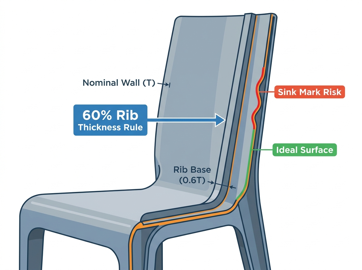
Rib thickness dictates quality: High back plastic chair reinforcement ribs must remain strictly at 50%–70% of nominal wall thickness to prevent visible sink marks on the aesthetic side.
Cooling and gating dictate cycle time: Tall backrests require multi-point hot runners and conformal cooling circuits to prevent uneven shrinkage and warpage over long flow lengths.
Interchangeability drives ROI: Modern tooling allows for interchangeable backrest inserts, enabling manufacturers to produce multiple chair styles from a single high-investment mold base.
Extending a backrest adds serious leverage to a chair. When a user leans back, the mechanical stress concentrates precisely where the backrest meets the seat pan. This junction acts as a pivotal hinge point. If you do not reinforce this critical area, the plastic will easily bend or fracture. Managing this risk profile requires precise calculations. Engineers must ensure the material can withstand dynamic human loads over years of continuous use.
Mold flow presents another harsh reality for manufacturers. A taller chair requires a significantly longer flow path for the molten resin. Plastic cools as it travels through the mold cavity. Premature freezing of this resin leads to short shots. You might also see weak weld lines form in the upper sections of the backrest. These weak points compromise both visual aesthetics and structural integrity. Maintaining consistent pressure and temperature across this extended path is exceptionally difficult.
Cooling dynamics further complicate production. Large surface areas remain highly susceptible to uneven cooling rates. The mold consists of a core (the inner side) and a cavity (the outer side). If these two halves cool at different speeds, the tall backrest will inevitably warp. Warping pulls the chair out of strict manufacturing tolerances. It negatively affects stackability, making storage and shipping a nightmare.
You need a strict evaluation lens when reviewing proposals. Always demand explicit Moldflow analysis reports from your tooling partner. These reports simulate the injection process digitally. They prove flow velocity and cooling uniformity before you commit to cutting expensive steel. A thorough Moldflow report exposes potential warpage issues early. It allows you to adjust gate locations and cooling lines proactively.
Thick plastic alone cannot solve structural weakness. Instead, you must use curvature as a primary structural beam. A smart integral chair backrest structural design incorporates sweeping ergonomic curves to distribute user weight efficiently. Different curvature profiles offer specific rigidity benefits:
U-Shape Profiles: These wrap around the user slightly, stiffening the side edges against backwards bending forces.
C-Curve Profiles: These support the lumbar region while naturally resisting vertical compression loads.
X-Back Profiles: Crossing structural bands distribute torsional stress across a wider surface area.
Your mold geometry must incorporate these curves flawlessly. However, designers must avoid creating undercuts. Undercuts complicate the ejection process and often require expensive mechanical sliders. Simple, flowing curves keep the mold architecture reliable.
Next, you must carefully manage wall thickness transitions. You must avoid abrupt changes in material thickness at all costs. Sudden shifts disrupt the flow of molten resin and cause intense internal stresses. The design should feature a gradual taper. Start with a thicker base at the seat junction to handle high leverage. Slowly taper the wall to a slightly thinner dimension near the top edge. This tapering technique maintains consistent injection pressure and eliminates flow hesitation.
Finally, we must consider the strict constraints of mold ejection. Taller backrests inherently require much deeper mold cavities. Pulling a large plastic part out of a deep steel cavity creates immense friction. The design must specify adequate draft angles along the entire backrest length. We generally recommend a draft angle of 1.5° to 3°. Proper draft prevents scuffing on the aesthetic surfaces. It ensures smooth demolding without stressing the warm, newly formed plastic.
You cannot simply add massive plastic blocks to strengthen a chair. Doing so creates severe cosmetic defects. Instead, you must apply the strict 60% rule for ribs. To reinforce the tall back without causing cosmetic sink marks on the front face, monitor your rib dimensions closely. The rib thickness at its base must never exceed 60% of the adjacent nominal wall thickness. Keeping high back plastic chair reinforcement ribs within this exact ratio ensures the front remains smooth and visually appealing.
Orientation determines how well ribs actually absorb stress. You must align ribs against specific load paths for maximum efficiency. Consider these specific configurations when reinforcing tall backrests:
Vertical Ribs: These run up the spine of the chair. They offer the best defense against backward bending loads when a heavy user leans back.
Diagonal or Intersecting Ribs: These form a lattice or diamond pattern on the rear surface. They provide ideal torsional stiffness, preventing the chair back from twisting sideways.
Gussets: These are small, sturdy triangular ribs. You place them precisely at the critical junction between the seat and the backrest. Gussets excel at dispersing highly concentrated leverage loads over a wider area.
Deep structural ribs carry significant tooling implications. When molten plastic rushes into a deep, thin rib cavity, it traps air. This trapped gas will ignite under high injection pressure, causing burn marks on the plastic. Therefore, thin ribs require specialized mold venting. You must also evaluate your mold maker’s EDM (Electrical Discharge Machining) capabilities. Achieving clean, highly polished, and deep rib cavities requires advanced EDM precision. Poorly machined ribs will stick during ejection and ruin the product.
High back chairs demand exceptional tooling durability. Pushing molten resin to the top of a tall backrest requires enormous injection pressures. Soft mold steels simply cannot survive this punishing environment. They will deform over time, leading to flash and dimensional errors. You must demand high-grade steel for the core and cavity. We strongly recommend specifying P20, 718H, or DIN 1.2738 steel. These robust materials guarantee parting line integrity and ensure mold longevity exceeding 500,000 cycles.
Steel Grade | Hardness (HRC) | Machinability | Best Application |
|---|---|---|---|
P20 | 28 - 32 | Excellent | Standard production, cost-effective bases. |
718H | 33 - 38 | Good | High-polish aesthetic cavity surfaces. |
DIN 1.2738 | 34 - 38 | Good | Large, deep cavities requiring high toughness. |
Your gating strategy heavily influences product quality. A standard single-point gate fails miserably for large furniture pieces. You cannot fill a tall backrest from one location without causing severe warp or weld lines. A successful high back integral chair mould design requires an advanced multi-point hot runner system. We suggest evaluating proven systems like Yudo or Husky. You must position valve gates strategically along the extended flow path. This approach minimizes visual weld lines, reduces internal stress, and speeds up your overall cycle time.
Advanced cooling architectures keep production profitable. Standard straight-drilled water lines struggle to cool the varied topography of a tall backrest. The heat naturally concentrates in thick sections and deep rib junctions. You must mandate conformal cooling channels. These channels wrap closely around the complex geometry of the part. Furthermore, insert beryllium copper into high-heat zones. Beryllium copper transfers heat much faster than standard steel. This ensures uniform dimensional stability and cuts seconds off every production cycle.
Tooling requires massive capital investment. Smart manufacturers maximize their ROI through a modular design strategy. We call this the "One Mold, Multiple Designs" approach. Advanced toolmakers design a common, heavy-duty base block. This base forms the legs and the seat pan. They then utilize a modular core and cavity insert system for the backrest itself.
Tooling Approach | Initial Investment | SKU Flexibility | Production Risk |
|---|---|---|---|
Dedicated Monobloc Mold | Very High | Low (One fixed design) | Low (Fewer parting lines) |
Interchangeable Insert Mold | High (Base + Inserts) | Very High (Multiple styles) | Moderate (Requires precise fitting) |
The business impact of modular tooling transforms your catalog capabilities. You can easily switch between a solid ergonomic back, an X-back style, or a modern slatted backrest. You achieve this variety without purchasing entirely new $50,000+ molds for every single SKU. Swapping the inserts takes hours, not weeks. It keeps your machinery running and your product offerings fresh.
However, you must manage specific implementation risks. Interchangeable inserts naturally introduce more parting lines into the mold assembly. If the tooling tolerances fall short of perfection, molten plastic will bleed into these seams. This creates ugly flash on the finished chair. You must assess the mold maker's CNC precision capabilities carefully. Review their spotting and fitting processes thoroughly. Only partner with vendors who demonstrate obsessive attention to dimensional tolerances before committing to a modular design.
A highly successful high back chair mold relies on strict engineering discipline. You must balance ergonomic structural curves to distribute loads effectively. You must strictly ratio your reinforcement ribs to avoid cosmetic sink marks. Additionally, you need high-performance cooling and multi-point gating systems. These advanced systems prevent catastrophic warpage and ensure long-term part durability under heavy human use.
Prioritize mold manufacturing partners who lead conversations with Design for Manufacturability (DFM). They should provide comprehensive Moldflow analysis rather than merely quoting the lowest steel price. As your immediate next step, request a preliminary structural analysis of your proposed backrest design. Demand proof of cooling uniformity and flow velocities. Securing these engineering guarantees before signing the tooling contract protects your investment and ensures scalable production success.
A: Nominal wall thickness usually ranges from 4mm to 6mm, depending on the chosen material. Manufacturers typically use Polypropylene (PP) or Polycarbonate (PC). The true key lies in uniform transitions rather than absolute thickness. Gradual tapering ensures smooth material flow and prevents concentrated stress points.
A: This visual defect occurs when the rib is too thick relative to the main wall. The thicker mass of plastic shrinks unevenly as it cools, pulling the front surface inward. You must strictly limit rib bases to 50-70% of the adjacent wall thickness to prevent this.
A: Yes, gas-assist technology proves highly effective for hollowing out the outer frame or the chair legs. It increases structural rigidity while simultaneously reducing overall part weight. However, manufacturers use it less commonly for the flat, central plane of the backrest itself.
A: Cycle times vary based on machine tonnage, wall thickness, and the efficiency of the cooling design. However, a highly optimized mold utilizing conformal cooling and beryllium copper inserts can consistently achieve rapid cycle times between 45 and 65 seconds.


